
Ed Middlebrook 2017
—– and some cool machining stuff
Myth Racing Components was started as the need for assembly tools became apparent through conversations with other early hemi owners. The name “Myth” came from my BB/GS ’48 Austin “The Myth” which I raced in the ‘70’s. In most cases I have taken my own tools (primitive in respect to the tools offered on this site) and refined them to produce a precision product.
Please take the time to read the following “About Me” and some cool machining stuff. In addition, a “Tech Talk” section has been included which covers most of the components in the engine assembly as well as some tuning information. Please note: This is what works for me (and has been working for 50+ years). It is not a guarantee!
If you have questions, do not hesitate to give me a call or drop me an email. I would rather you ask a question than to learn the hard way (like I did).
I started hopping-up my ’57 Chevy street car after I got out of high school in 1960. I added a stroker kit with 12:1 pistons and Engle cam to produce a whopping 341 ci.
In 1962 I went to work for Douglas Aircraft Co. in the machine shop where I ran their first 4-axis Numerically Controlled (now CNC) machine.
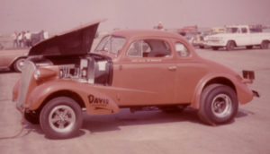 Shortly thereafter I broke the crank in my Chevy so opted to sell the car with a stock engine and put my repaired 341” in a ’37 Chevy for drag racing.
With a little extra cash from working seven days a week, I purchased Hilborn injectors, an Engle roller cam, Vertex magneto and some ported heads. This heavyweight ran 12.30’s at Lions. After breaking yet another “welded” stroker I purchased a destroked 265” Bonneville short block (258”) with a chrome crank and one bad throw for $25. Crankshaft Company repaired the throw and afterwards warned me I would have very little clearance. Upon checking I found the clearances were about .0002 – .0005!
Since I was out of “mad money” I assembled the engine, put in my 6.14 gears and headed for the track. This combo ran 11.72 @ 116 mph ??? I never had any bearing problems.
In ’69 I traded the ’37 Chevy for a ’48 Austin of England. Some work had been done on the stock chassis but that was it. I learned that Fred Seay (Donovan Engineering) was selling the supercharged 331” hemi out of his dragster and decided that was exactly what my Austin needed.
Also in ’69 I was recruited by the N/C programming department (by now McDonnell Douglas) to make the switch to a programmer rather than a machine operator. One of my first assignments (paired with an experienced programmer) was the first machined part on the DC10 which was the front window frame for the cockpit.
Along with the new job came some additional pay and a 68-hour work week. I now had a little extra to spend on the car but even less time to spend on the construction.![]()
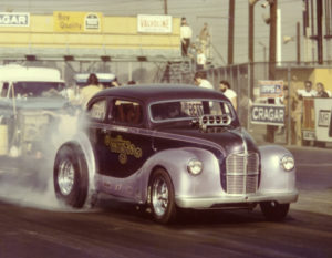 In summer of ’72 the car was completed and I made the first runs at Lions with the BB/GS Austin which netted et’s in the high-nines. With no experience running a supercharged gasoline powered engine, I soon found how easy it was to knock out pistons and rings. After a lot of pistons and tuning changes I was finally able to run in the low nines at speeds around 150 mph.
By the mid-‘70’s I had replaced the B&M Clutchflite with a B&J 3-speed, acquired some good heads from Steve Woods and more or less cured the burned piston/ring problem (more on that in the Tech Talk section). With a .060 over 354 @ 2850 lbs (legal BB/GS), I eventually ran 8.57 @ 162 mph. This was accomplished with 14-32×15 tires, 5.57 gears and a launch rpm of 9000+ (peg the tach. and slide your foot off the clutch). FYI: I ran a 40 lb. flywheel and a 10” McLeod “Long” dual disc setup with 800 lbs. of static spring pressure. Getting a hemi to run isn’t rocket science. I never broke any rotating parts running at over 9000 rpm. One reason I could do this was the light piston/rod assembly associated with a supercharged gas engine as well as a very light valve train.
By the late ‘70’s the Austin was long gone but the engine sat on an engine stand in my shop as a reminder to someday find it a new home. The “someday” took a while since I was now the manager of the Boeing parts programming group in Huntington Beach, CA. As with these types of jobs and especially corporations like Boeing, you don’t stray far from home – work is your life. Early retirement in 2000, five years taking care of my mother and relocating to Prescott, AZ brings us to 2008.
My cousin lives in Phoenix and asked me to look at a 6.00 certified Spitzer Fiat Topolino altered. He was looking to upgrade but decided not to buy this car. The light bulb goes off, mama approves and I’m back in business.
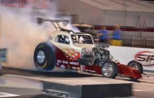 I refreshed (as best I could without buying everything new) the same tired hemi, added a powerglide and headed to the races to run the 7.60 nostalgia category. At 2200 lbs I expected something spectacular – well that didn’t happen. Running gasoline, it ran 7.91 @ 169 mph at the 2008 Bakersfield “March Meet”. I’m sure the less than expected performance was mainly due to operating at a lower rpm (8000 max), 4.30 gears and a change in transmissions along with a lower launch rpm.
For the 2009 California Hot Rod Reunion I switched to alcohol and didn’t see the 170’s. It ran 7.40 @ 185 on the second run. Now for the first time in my life I had to slow the car down to make the NE1 index.
For the 7.60 index I’m practically running a “street” setup – 8% underdriven 6.71 at 12 lbs boost with the timing at 22 degrees. Still runs about 175 mph at low altitude. I also run with the Western Fuel Altereds where we can run as fast as we can. In 2014, I purchased a 511″ TFX 92 to see if I could keep up with the big boys. After two years of tuning changes my best wasn’t much better than with the early hemi (7.20 @ 188). For 2016 I decided the engine might like more rpm to get the air flowing in the huge top fuel cylinder head ports so switched from a 4.10 to a 4.30 gear. The result was a 6.61 @ 209.91. That’s over 20 mph from one change!
If you want to run a hemi on gas, alcohol or a low percentage of nitro check out the “Tech Talk” section and I’ll tell you how to safely do it with little or no parts breakage. I’m talking racing – not street (although most applies). I have NEVER run a carburetor on a race car so don’t ask for advice in this area.
If you got this far, THANKS FOR READING!
Ed Middlebrook, Myth Racing Components
Machining Background
This is just part of “who I am” and may be of interest to those interested in machining since I was the first to create a machining program utilizing CAM software.
I look at the billet blocks and heads being done on a CNC machine and I’m impressed. But, I’ve been there so just normal evolution.
In the early ’70’s, Pat Hanratty (father of CAD/CAM) contacted the manager of our systems group at McDonnell Douglas in Santa Monica, CA. He was looking for a platform to beta test his new software and I was chosen to assist from a part programmer’s standpoint.
Instead of a programmer created paper model and hand written code, I would utilize a CAD model along with Pat’s software to create the cutter path. Pat named it CAM (Computer Aided Manufacturing).
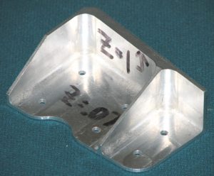
Pat knew nothing about machining but after a little “tutoring” came up with a pretty nice product. The 2″ x 3″ part pictured here is the first part anywhere to be machined utilizing a CAM program.
Another first!
Ever wonder what the piece of billet aluminum for an engine block costs? Expensive! How many pieces did it take before a quality block was produced? Many!
This is the problem we ran into when machining parts for Space Station in the early ’90’s. Our “standard” process allowed for (3) parts in order to perfect the machining program. Space Station was a different animal. One part for test and one for flight.
The part pictured below is one of the “bulkheads” for the modular Space Station assembly. The numerous hold-down tabs around the part were removed after machining. These numerous tabs were added because we “thought” significant warpage would pull the threads out of the table. As we would learn, the 7050 T6 material was very stable and warpage was minimal. If you’re into machining, you’ve probably dealt with warpage. Our normal process was to rough one side, flip, rough and finish the second side, flip, finish the first side. Once we found how stable the 7050 was, we were able to rough and finish each side thus saving one extensive setup – this saved hours of valuable machine time. Overall warpage was only .060! The only problem we had was the engineering design called for .030. A visit to the assembly fixture showed a little thumb pressure could move the center of the part .250 in each direction. Engineering subsequently relented and changed the design tolerance to +/- .060. The shape was hexagonal to fit inside the space shuttle bay. As compared to the size and cost of material for a billet engine block, the solid 7050 aluminum billet for this guy was 244″ x 244″ x 6″ thick!
Other than a pen plotter and review of thousands of lines of code, the survival rate of the first finished part was always in question.
As fate would have it, on one operation the cutter selected by the operator was 1.250″ diameter whereas the tool path was created for a 1″ cutter. The results? Pocket wall undercut by 1/2 the diameter difference = .125 = thin wall.
Ed and his boss are immediately called to the office of the vice president of Space Station. Unfamiliar with our “process”, the VP had assured the government all first parts would be perfect. An impossible task!
As always, the question arises “How do we avoid this happening again?”. Fortunately, we had just reviewed some new verification software (Vericut) but couldn’t get authorization for the $230,000 expenditure. With a snap of the VP’s finger we had our software. No one in the country had this software so we were ahead of the game.
If you’ve ever wondered how errors are minimized, this is the answer – simplified.
The engineer creates a solid model using graphics software – in our case Unigraphics.
The machined parts programmer creates the machining program utilizing the solid model and sophisticated CAM software.
Verification software takes the cutting tool centerline coordinates from the machining program, adds the cutter diameter along with depth of cut and removes that amount of material from the programmer described stock (billet). Whatever is left “should” closely represent the original engineer created solid model.
This new solid “model” is overlaid with the original engineering model and someone assigned to make the visual check determines if the machining program is good. My group eventually developed a piece of software to analyze any differences.
We are now fairly confident the tool path is correct, but as we would find out, there are many ways to ruin a part other than the cutter path. One of those was described above – selecting the wrong cutter. This is a plus for automated tool changers like the ones used to machine an engine block. That is, if the cutter is supplied with the correct diameter, corner radius, length, etc.
Modern verification software has evolved to include a solid model of the milling or turning machine, tool holder, etc to minimize the chances of a crash.
OK, one last story for drag racers
Around 1970, I was the lead machined parts programmer on the guidance section of the upper stage (payload) of an ABM (anti ballistic missile) high speed interceptor. The project was appropriately named “Upstage”. The purpose was to demonstrate to the Russians our ability to “kill” an incoming ballistic missile. This project was not classified.
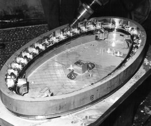
Machining the elliptical cone base.
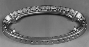
Inner and outer aluminum pieces were machined to create a gas distribution channel beneath the round ports you see in the picture (more visible in the finished part below). The two pieces were then electron beam welded together to create the piece you see here.
Each of the small ports would later be fitted with computer activated solenoids to release a gas into the atmosphere. The outer surface (not yet machined in this picture) was an elliptical cone with distribution fins fitted on the exterior opposite the small ports.
The four pads on the interior are for mounting the compressed gas bottle (from opposite side).
The release of the gas at various points around the elliptical cone caused a low pressure area which guided the payload. It worked perfectly and the technology was used to guide future missiles.
Finished machined part
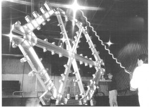
Of particular interest was being able to make a 45 degree turn at over 100 g’s and then accelerate to about 400 g’s all in one second (total burn time). Here’s a picture from www.secretprojects.co.uk.
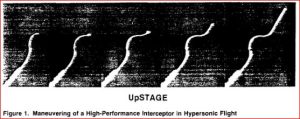
The test vehicle achieved 8400 fps or 0-5700 mph in the first second and made the 45 degree turn.
Pretty cool for the 70’s. And we’re thinking 3 g’s in our drag car is a lot.